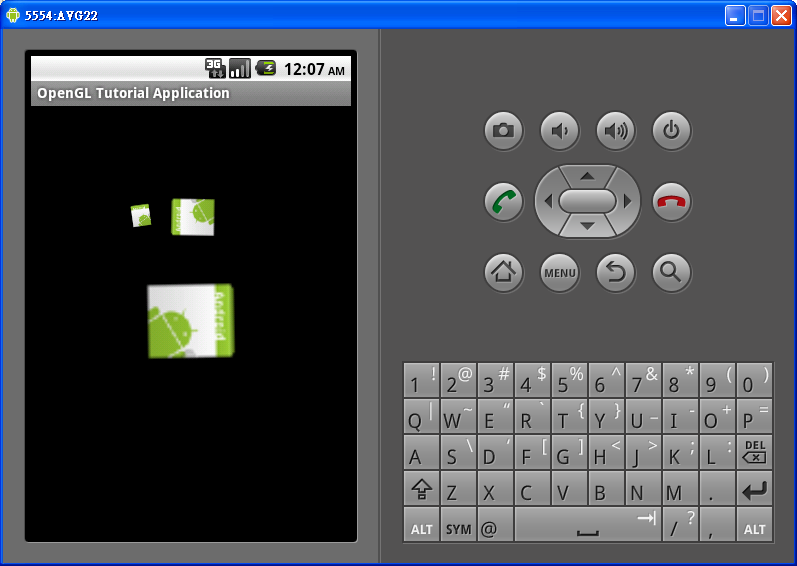
經測試其重要範例執行畫面如下:


    protected void onCreate(Bundle savedInstanceState) {
        super.onCreate(savedInstanceState);

        // Create our Preview view and set it as the content of our
        // Activity
        mGLSurfaceView = new TouchSurfaceView(this);
        setContentView(mGLSurfaceView);
        mGLSurfaceView.requestFocus();
        mGLSurfaceView.setFocusableInTouchMode(true);
    }
    @Override public boolean onTrackballEvent(MotionEvent e) {
        mRenderer.mAngleX += e.getX() * TRACKBALL_SCALE_FACTOR;
        mRenderer.mAngleY += e.getY() * TRACKBALL_SCALE_FACTOR;
        requestRender();
        return true;
    }

    @Override public boolean onTouchEvent(MotionEvent e) {
        float x = e.getX();
        float y = e.getY();
        switch (e.getAction()) {
        case MotionEvent.ACTION_MOVE:
            float dx = x - mPreviousX;
            float dy = y - mPreviousY;
            mRenderer.mAngleX += dx * TOUCH_SCALE_FACTOR;
            mRenderer.mAngleY += dy * TOUCH_SCALE_FACTOR;
            requestRender();
        }
        mPreviousX = x;
        mPreviousY = y;
        return true;
    }

package com.example.opengl;

import javax.microedition.khronos.egl.EGLConfig;
import javax.microedition.khronos.opengles.GL10;

import android.app.Activity;
import android.content.Context;
import android.opengl.GLSurfaceView;
import android.os.Bundle;
import android.view.MotionEvent;

public class TouchRotateActivity extends Activity {
    @Override
    protected void onCreate(Bundle savedInstanceState) {
        super.onCreate(savedInstanceState);

        // Create our Preview view and set it as the content of our
        // Activity
        mGLSurfaceView = new TouchSurfaceView(this);
        setContentView(mGLSurfaceView);
        mGLSurfaceView.requestFocus();
        mGLSurfaceView.setFocusableInTouchMode(true);
    }

    @Override
    protected void onResume() {
        // Ideally a game should implement onResume() and onPause()
        // to take appropriate action when the activity looses focus
        super.onResume();
        mGLSurfaceView.onResume();
    }

    @Override
    protected void onPause() {
        // Ideally a game should implement onResume() and onPause()
        // to take appropriate action when the activity looses focus
        super.onPause();
        mGLSurfaceView.onPause();
    }

    private GLSurfaceView mGLSurfaceView;
}

/**
 * Implement a simple rotation control.
 *
 */
class TouchSurfaceView extends GLSurfaceView {

    public TouchSurfaceView(Context context) {
        super(context);
        mRenderer = new CubeRenderer();
        setRenderer(mRenderer);
        setRenderMode(GLSurfaceView.RENDERMODE_WHEN_DIRTY);
    }

    @Override public boolean onTrackballEvent(MotionEvent e) {
        mRenderer.mAngleX += e.getX() * TRACKBALL_SCALE_FACTOR;
        mRenderer.mAngleY += e.getY() * TRACKBALL_SCALE_FACTOR;
        requestRender();
        return true;
    }

    @Override public boolean onTouchEvent(MotionEvent e) {
        float x = e.getX();
        float y = e.getY();
        switch (e.getAction()) {
        case MotionEvent.ACTION_MOVE:
            float dx = x - mPreviousX;
            float dy = y - mPreviousY;
            mRenderer.mAngleX += dx * TOUCH_SCALE_FACTOR;
            mRenderer.mAngleY += dy * TOUCH_SCALE_FACTOR;
            requestRender();
        }
        mPreviousX = x;
        mPreviousY = y;
        return true;
    }

    /**
     * Render a cube.
     */
    private class CubeRenderer implements GLSurfaceView.Renderer {
        public CubeRenderer() {
            mCube = new Cube();
        }

        public void onDrawFrame(GL10 gl) {
            /*
             * Usually, the first thing one might want to do is to clear
             * the screen. The most efficient way of doing this is to use
             * glClear().
             */

            gl.glClear(GL10.GL_COLOR_BUFFER_BIT | GL10.GL_DEPTH_BUFFER_BIT);

            /*
             * Now we're ready to draw some 3D objects
             */

            gl.glMatrixMode(GL10.GL_MODELVIEW);
            gl.glLoadIdentity();
            gl.glTranslatef(0, 0, -3.0f);
            gl.glRotatef(mAngleX, 0, 1, 0);
            gl.glRotatef(mAngleY, 1, 0, 0);

            gl.glEnableClientState(GL10.GL_VERTEX_ARRAY);
            gl.glEnableClientState(GL10.GL_COLOR_ARRAY);

            mCube.draw(gl);
        }

        public void onSurfaceChanged(GL10 gl, int width, int height) {
             gl.glViewport(0, 0, width, height);

             /*
              * Set our projection matrix. This doesn't have to be done
              * each time we draw, but usually a new projection needs to
              * be set when the viewport is resized.
              */

             float ratio = (float) width / height;
             gl.glMatrixMode(GL10.GL_PROJECTION);
             gl.glLoadIdentity();
             gl.glFrustumf(-ratio, ratio, -1, 1, 1, 10);
        }

        public void onSurfaceCreated(GL10 gl, EGLConfig config) {
            /*
             * By default, OpenGL enables features that improve quality
             * but reduce performance. One might want to tweak that
             * especially on software renderer.
             */
            gl.glDisable(GL10.GL_DITHER);

            /*
             * Some one-time OpenGL initialization can be made here
             * probably based on features of this particular context
             */
             gl.glHint(GL10.GL_PERSPECTIVE_CORRECTION_HINT,
                     GL10.GL_FASTEST);


             gl.glClearColor(1,1,1,1);
             gl.glEnable(GL10.GL_CULL_FACE);
             gl.glShadeModel(GL10.GL_SMOOTH);
             gl.glEnable(GL10.GL_DEPTH_TEST);
        }
        private Cube mCube;
        public float mAngleX;
        public float mAngleY;
    }

    private final float TOUCH_SCALE_FACTOR = 180.0f / 320;
    private final float TRACKBALL_SCALE_FACTOR = 36.0f;
    private CubeRenderer mRenderer;
    private float mPreviousX;
    private float mPreviousY;
}


package com.example.opengl;

import java.nio.ByteBuffer;
import java.nio.ByteOrder;
import java.nio.IntBuffer;

import javax.microedition.khronos.opengles.GL10;

public class Cube {
    public Cube()
    {
        int one = 0x10000;
        int vertices[] = {
                -one, -one, -one,
                one, -one, -one,
                one,  one, -one,
                -one,  one, -one,
                -one, -one,  one,
                one, -one,  one,
                one,  one,  one,
                -one,  one,  one,
        };

        int colors[] = {
                0,    0,    0,  one,
                one,    0,    0,  one,
                one,  one,    0,  one,
                0,  one,    0,  one,
                0,    0,  one,  one,
                one,    0,  one,  one,
                one,  one,  one,  one,
                0,  one,  one,  one,
        };

        byte indices[] = {
                0, 4, 5,    0, 5, 1,
                1, 5, 6,    1, 6, 2,
                2, 6, 7,    2, 7, 3,
                3, 7, 4,    3, 4, 0,
                4, 7, 6,    4, 6, 5,
                3, 0, 1,    3, 1, 2
        };

        // Buffers to be passed to gl*Pointer() functions
        // must be direct, i.e., they must be placed on the
        // native heap where the garbage collector cannot
        // move them.
        //
        // Buffers with multi-byte datatypes (e.g., short, int, float)
        // must have their byte order set to native order

        ByteBuffer vbb = ByteBuffer.allocateDirect(vertices.length*4);
        vbb.order(ByteOrder.nativeOrder());
        mVertexBuffer = vbb.asIntBuffer();
        mVertexBuffer.put(vertices);
        mVertexBuffer.position(0);

        ByteBuffer cbb = ByteBuffer.allocateDirect(colors.length*4);
        cbb.order(ByteOrder.nativeOrder());
        mColorBuffer = cbb.asIntBuffer();
        mColorBuffer.put(colors);
        mColorBuffer.position(0);

        mIndexBuffer = ByteBuffer.allocateDirect(indices.length);
        mIndexBuffer.put(indices);
        mIndexBuffer.position(0);
    }

    public void draw(GL10 gl)
    {
        gl.glFrontFace(gl.GL_CW);
        gl.glVertexPointer(3, gl.GL_FIXED, 0, mVertexBuffer);
        gl.glColorPointer(4, gl.GL_FIXED, 0, mColorBuffer);
        gl.glDrawElements(gl.GL_TRIANGLES, 36, gl.GL_UNSIGNED_BYTE, mIndexBuffer);
    }

    private IntBuffer   mVertexBuffer;
    private IntBuffer   mColorBuffer;
    private ByteBuffer  mIndexBuffer;
}


OpenGLActivity.java 程式列表
package nkut.cce.smartliving.opengl;

import android.app.Activity;
import android.graphics.Bitmap;
import android.graphics.BitmapFactory;
import android.opengl.GLSurfaceView;
import android.os.Bundle;

public class OpenGLActivity extends Activity {
 /** Called when the activity is first created. */

 @Override
 public void onCreate(Bundle savedInstanceState) {
  super.onCreate(savedInstanceState);
  GLSurfaceView view = new GLSurfaceView(this);
  OpenGLRenderer render = new OpenGLRenderer();

  // 載入位元圖
  Bitmap bitmap = BitmapFactory.decodeResource(getResources(),
    R.drawable.icon);
  render.setBitmap(bitmap);

  view.setRenderer(render);

  setContentView(view);
 }
}

OpenGLRender.java程式列表

package nkut.cce.smartliving.opengl;

import javax.microedition.khronos.egl.EGLConfig;
import javax.microedition.khronos.opengles.GL10;

import android.graphics.Bitmap;
import android.opengl.GLSurfaceView.Renderer;
import android.opengl.GLU;

public class OpenGLRenderer implements Renderer {
 private Square square;
 private float angle = 0;

 public OpenGLRenderer() {
  // 初始化
  square = new Square();
 }

 @Override
 public void onDrawFrame(GL10 gl) {
  // TODO Auto-generated method stub
  // 清除螢幕和深度緩衝區
  gl.glClear(GL10.GL_COLOR_BUFFER_BIT | GL10.GL_DEPTH_BUFFER_BIT);
  // 以單位矩陣取代目前的矩陣
  gl.glLoadIdentity();
  // Z軸轉置 10 單位
  gl.glTranslatef(0, 0, -10);

  // 第一個方形
  // 存儲目前陣列
  gl.glPushMatrix();
  // 反時鐘旋轉
  gl.glRotatef(angle, 0, 0, 1);
  // 畫出第一個方形
  square.draw(gl);
  // 復原成最後的矩陣
  gl.glPopMatrix();

  // 第二個方形
  // 存儲目前陣列
  gl.glPushMatrix();
  // 在移動前先旋轉, 讓第二個方形圍繞著第一個方形旋轉
  gl.glRotatef(-angle, 0, 0, 1);
  // 移動第二個方形
  gl.glTranslatef(2, 0, 0);
  // 調整其大小為第一個方形的一半
  gl.glScalef(.5f, .5f, .5f);
  // 畫出第二個方形
  square.draw(gl);

  // 第三個方形
  // 存儲目前陣列
  gl.glPushMatrix();
  // 讓第三個方形圍繞著第二個方形旋轉
  gl.glRotatef(-angle, 0, 0, 1);
  // 移動第三個方形
  gl.glTranslatef(2, 0, 0);
  // 調整其大小為第二個方形的一半
  gl.glScalef(.5f, .5f, .5f);
  // 以自己為中心旋轉
  gl.glRotatef(angle * 10, 0, 0, 1);
  // 畫出第三個方形.
  square.draw(gl);

  // 復原成第三個方形前的矩陣
  gl.glPopMatrix();
  // 復原成第二個方形前的矩陣.
  gl.glPopMatrix();

  // 增加角度
  angle++;
 }

 @Override
 public void onSurfaceChanged(GL10 gl, int width, int height) {
  // TODO Auto-generated method stub
  // 設定新視域視窗的大小
  gl.glViewport(0, 0, width, height);
  // 選擇投射的陣列模式
  gl.glMatrixMode(GL10.GL_PROJECTION);
  // 重設投射陣
  gl.glLoadIdentity();
  // 計算視窗的寬高比率
  GLU.gluPerspective(gl, 45.0f, (float) width / (float) height, 0.1f,
    100.0f);
  // 選擇MODELVIEW陣列
  gl.glMatrixMode(GL10.GL_MODELVIEW);
  // 重設MODELVIEW陣列
  gl.glLoadIdentity();
 }

 @Override
 public void onSurfaceCreated(GL10 gl, EGLConfig config) {
  // TODO Auto-generated method stub
  // 設定背景顏色為黑色, 格式是RGBA
  gl.glClearColor(0.0f, 0.0f, 0.0f, 0.5f);
  // 設定流暢的陰影模式
  gl.glShadeModel(GL10.GL_SMOOTH);
  // 深度緩區的設定
  gl.glClearDepthf(1.0f);
  // 啟動深度的測試
  gl.glEnable(GL10.GL_DEPTH_TEST);
  // GL_LEQUAL深度函式測試
  gl.glDepthFunc(GL10.GL_LEQUAL);
  // 設定很好的角度計算模式
  gl.glHint(GL10.GL_PERSPECTIVE_CORRECTION_HINT, GL10.GL_NICEST);
 }

 public void setBitmap(Bitmap bitmap) {
  // TODO Auto-generated method stub
  square.setBitmap(bitmap);
 }
}

square.java程式列表

package nkut.cce.smartliving.opengl;

import java.nio.ByteBuffer;
import java.nio.ByteOrder;
import java.nio.FloatBuffer;
import java.nio.ShortBuffer;

import javax.microedition.khronos.opengles.GL10;

import android.graphics.Bitmap;
import android.opengl.GLUtils;

public class Square {
 // 點的陣列
 private float vertices[] = { -1.0f, 1.0f, 0.0f, // 0, 左上角
   -1.0f, -1.0f, 0.0f, // 1, 左下角
   1.0f, -1.0f, 0.0f, // 2, 右下角
   1.0f, 1.0f, 0.0f, // 3, 右上角
 };

 // 將顏色資訊對應到點陣列上
 float[] colors = { 1f, 0f, 0f, 1f, // 左上角 0 red
   0f, 1f, 0f, 1f, // 左下角 1 green
   0f, 0f, 1f, 1f, // 右下角 2 blue
   1f, 0f, 1f, 1f, // 右上角 3 magenta
 };

 // 質地坐標
 float texture[] = { 0.0f, 0.0f, //
   0.0f, 1.0f, //
   1.0f, 1.0f, //
   1.0f, 0.0f, //
 };
 // 連接點的次序
 private short[] indices = { 0, 1, 2, 0, 2, 3 };

 // 點的緩衝區
 private FloatBuffer vertexBuffer;

 // 索引值緩衝區
 private ShortBuffer indexBuffer;

 // 顏色緩衝區
 private FloatBuffer colorBuffer;

 // 質地緩衝區
 private FloatBuffer textureBuffer;

 Bitmap bitmap;

 public Square() {
  // 浮點數是4位元組因此需要把點陣列長度乘以4
  ByteBuffer vbb = ByteBuffer.allocateDirect(vertices.length * 4);
  vbb.order(ByteOrder.nativeOrder());
  vertexBuffer = vbb.asFloatBuffer();
  vertexBuffer.put(vertices);
  vertexBuffer.position(0);

  // 短整數是2位元組因此需要把點陣列長度乘以2
  ByteBuffer ibb = ByteBuffer.allocateDirect(indices.length * 2);
  ibb.order(ByteOrder.nativeOrder());
  indexBuffer = ibb.asShortBuffer();
  indexBuffer.put(indices);
  indexBuffer.position(0);

  // 浮點數是4位元組,顏色(RGBA)
  ByteBuffer cbb = ByteBuffer.allocateDirect(colors.length * 4);
  cbb.order(ByteOrder.nativeOrder());
  colorBuffer = cbb.asFloatBuffer();
  colorBuffer.put(colors);
  colorBuffer.position(0);

  ByteBuffer byteBuf = ByteBuffer.allocateDirect(texture.length * 4);
  byteBuf.order(ByteOrder.nativeOrder());
  textureBuffer = byteBuf.asFloatBuffer();
  textureBuffer.put(texture);
  textureBuffer.position(0);
 }

 /**
  * 畫圖函式
  *
  * @param gl
  */
 public void draw(GL10 gl) {
  // 逆時鐘
  gl.glFrontFace(GL10.GL_CCW);
  // 啟動CULL_FACE
  gl.glEnable(GL10.GL_CULL_FACE);
  // 刪除多邊形的背景
  gl.glCullFace(GL10.GL_BACK);

  // 啟動點的緩衝區
  gl.glEnableClientState(GL10.GL_VERTEX_ARRAY);
  // 指定位置和資料格式
  gl.glVertexPointer(3, GL10.GL_FLOAT, 0, vertexBuffer);

  // 在渲染期間啟用顏色緩衝區
  gl.glEnableClientState(GL10.GL_COLOR_ARRAY);

  // 指定顏色緩衝區。
  gl.glColorPointer(4, GL10.GL_FLOAT, 0, colorBuffer);

  // 建立質地陣列
  int[] textures = new int[1];
  // 告訴OpenGL產生第幾個質地
  gl.glGenTextures(1, textures, 0);

  // 指定要用那一質地
  gl.glBindTexture(GL10.GL_TEXTURE_2D, textures[0]);

  // 載入質地位元圖
  GLUtils.texImage2D(GL10.GL_TEXTURE_2D, 0, bitmap, 0);

  // 啟動質地功能
  gl.glEnable(GL10.GL_TEXTURE_2D);

  // 使用UV坐標
  gl.glEnableClientState(GL10.GL_TEXTURE_COORD_ARRAY);

  // 指定質地緩衝區
  gl.glTexCoordPointer(2, GL10.GL_FLOAT, 0, textureBuffer);  // 以三點劃出三角形
  gl.glDrawElements(GL10.GL_TRIANGLES, indices.length,
    GL10.GL_UNSIGNED_SHORT, indexBuffer);

  // 除能點的緩衝區
  gl.glDisableClientState(GL10.GL_VERTEX_ARRAY);
  // 除能CULL_FACE
  gl.glDisable(GL10.GL_CULL_FACE);

  // 除能UV坐標
  gl.glDisableClientState(GL10.GL_TEXTURE_COORD_ARRAY);

  // 除能質地的使用
  gl.glDisable(GL10.GL_TEXTURE_2D); }

 public void setBitmap(Bitmap bitmap) {
  // TODO Auto-generated method stub
  this.bitmap = bitmap;
 }}

import java.nio.ByteBuffer;
import java.nio.ByteOrder;
import java.nio.FloatBuffer;
import java.nio.ShortBuffer;

import javax.microedition.khronos.opengles.GL10;

public class Square {
 // 點的陣列
 private float vertices[] = { -1.0f, 1.0f, 0.0f, // 0, 左上角
   -1.0f, -1.0f, 0.0f, // 1, 左下角
   1.0f, -1.0f, 0.0f, // 2, 右下角
   1.0f, 1.0f, 0.0f, // 3, 右上角
 };

 // 將顏色資訊對應到點陣列上
 float[] colors = { 1f, 0f, 0f, 1f, // 左上角 0 red
   0f, 1f, 0f, 1f, // 左下角 1 green
   0f, 0f, 1f, 1f, // 右下角 2 blue
   1f, 0f, 1f, 1f, // 右上角 3 magenta
 };

 // 連接點的次序
 private short[] indices = { 0, 1, 2, 0, 2, 3 };

 // 點的緩衝區
 private FloatBuffer vertexBuffer;

 // 索引值緩衝區
 private ShortBuffer indexBuffer;

 // 顏色緩衝區
 private FloatBuffer colorBuffer;

 public Square() {
  // 浮點數是4位元組因此需要把點陣列長度乘以4
  ByteBuffer vbb = ByteBuffer.allocateDirect(vertices.length * 4);
  vbb.order(ByteOrder.nativeOrder());
  vertexBuffer = vbb.asFloatBuffer();
  vertexBuffer.put(vertices);
  vertexBuffer.position(0);

  // 短整數是2位元組因此需要把點陣列長度乘以2
  ByteBuffer ibb = ByteBuffer.allocateDirect(indices.length * 2);
  ibb.order(ByteOrder.nativeOrder());
  indexBuffer = ibb.asShortBuffer();
  indexBuffer.put(indices);
  indexBuffer.position(0);

  // 浮點數是4位元組,顏色(RGBA) * 4 位元組
  ByteBuffer cbb = ByteBuffer.allocateDirect(colors.length * 4);
  cbb.order(ByteOrder.nativeOrder());
  colorBuffer = cbb.asFloatBuffer();
  colorBuffer.put(colors);
  colorBuffer.position(0);
 }

 /**
  * 畫圖函式
  *
  * @param gl
  */
 public void draw(GL10 gl) {
  // 逆時鐘
  gl.glFrontFace(GL10.GL_CCW);
  // 啟動CULL_FACE
  gl.glEnable(GL10.GL_CULL_FACE);
  // 刪除多邊形的背景
  gl.glCullFace(GL10.GL_BACK);

  // 啟動點的緩衝區
  gl.glEnableClientState(GL10.GL_VERTEX_ARRAY);
  // 指定位置和資料格式
  gl.glVertexPointer(3, GL10.GL_FLOAT, 0, vertexBuffer);

  // 在渲染期間啟用顏色緩衝區
  gl.glEnableClientState(GL10.GL_COLOR_ARRAY);

  // 指定顏色緩衝區。
  gl.glColorPointer(4, GL10.GL_FLOAT, 0, colorBuffer);

  // 以三點劃出三角形
  gl.glDrawElements(GL10.GL_TRIANGLES, indices.length,
    GL10.GL_UNSIGNED_SHORT, indexBuffer);

  // 除能點的緩衝區
  gl.glDisableClientState(GL10.GL_VERTEX_ARRAY);
  // 除能CULL_FACE
  gl.glDisable(GL10.GL_CULL_FACE);
 }
}


package nkut.cce.smartliving.opengl;

import javax.microedition.khronos.egl.EGLConfig;
import javax.microedition.khronos.opengles.GL10;

import android.opengl.GLSurfaceView.Renderer;
import android.opengl.GLU;

public class OpenGLRenderer implements Renderer {
 private Square square;
 private float angle = 0;

 public OpenGLRenderer() {
  // 初始化
  square = new Square();
 }

 @Override
 public void onDrawFrame(GL10 gl) {
  // TODO Auto-generated method stub
  // 清除螢幕和深度緩衝區
  gl.glClear(GL10.GL_COLOR_BUFFER_BIT | GL10.GL_DEPTH_BUFFER_BIT);
  // 以單位矩陣取代目前的矩陣
  gl.glLoadIdentity();

  // Z軸轉置 10 單位
  gl.glTranslatef(0, 0, -10);

  // 第一個方形
  // 存儲目前陣列
  gl.glPushMatrix();
  // 反時鐘旋轉
  gl.glRotatef(angle, 0, 0, 1);
  // 畫出第一個方形
  square.draw(gl);
  // 復原成最後的矩陣
  gl.glPopMatrix();

  // 第二個方形
  // 存儲目前陣列
  gl.glPushMatrix();
  // 在移動前先旋轉, 讓第二個方形圍繞著第一個方形旋轉
  gl.glRotatef(-angle, 0, 0, 1);
  // 移動第二個方形
  gl.glTranslatef(2, 0, 0);
  // 調整其大小為第一個方形的一半
  gl.glScalef(.5f, .5f, .5f);
  // 畫出第二個方形
  square.draw(gl);

  // 第三個方形
  // 存儲目前陣列
  gl.glPushMatrix();
  // 讓第三個方形圍繞著第二個方形旋轉
  gl.glRotatef(-angle, 0, 0, 1);
  // 移動第三個方形
  gl.glTranslatef(2, 0, 0);
  // 調整其大小為第二個方形的一半
  gl.glScalef(.5f, .5f, .5f);
  // 以自己為中心旋轉
  gl.glRotatef(angle * 10, 0, 0, 1);
  // 畫出第三個方形.
  square.draw(gl);

  // 復原成第三個方形前的矩陣
  gl.glPopMatrix();
  // 復原成第二個方形前的矩陣.
  gl.glPopMatrix();

  // 增加角度
  angle++;

 }

 @Override
 public void onSurfaceChanged(GL10 gl, int width, int height) {
  // TODO Auto-generated method stub
  // 設定新視域視窗的大小
  gl.glViewport(0, 0, width, height);
  // 選擇投射的陣列模式
  gl.glMatrixMode(GL10.GL_PROJECTION);
  // 重設投射陣
  gl.glLoadIdentity();
  // 計算視窗的寬高比率
  GLU.gluPerspective(gl, 45.0f, (float) width / (float) height, 0.1f,
    100.0f);
  // 選擇MODELVIEW陣列
  gl.glMatrixMode(GL10.GL_MODELVIEW);
  // 重設MODELVIEW陣列
  gl.glLoadIdentity();
 }

 @Override
 public void onSurfaceCreated(GL10 gl, EGLConfig config) {
  // TODO Auto-generated method stub
  // 設定背景顏色為黑色, 格式是RGBA
  gl.glClearColor(0.0f, 0.0f, 0.0f, 0.5f);
  // 設定流暢的陰影模式
  gl.glShadeModel(GL10.GL_SMOOTH);
  // 深度緩區的設定
  gl.glClearDepthf(1.0f);
  // 啟動深度的測試
  gl.glEnable(GL10.GL_DEPTH_TEST);
  // GL_LEQUAL深度函式測試
  gl.glDepthFunc(GL10.GL_LEQUAL);
  // 設定很好的角度計算模式
  gl.glHint(GL10.GL_PERSPECTIVE_CORRECTION_HINT, GL10.GL_NICEST);
 }

}

 // 點的陣列
 private float vertices[] = { -1.0f, 1.0f, 0.0f, // 0, 左上角
   -1.0f, -1.0f, 0.0f, // 1, 左下角
   1.0f, -1.0f, 0.0f, // 2, 右下角
   1.0f, 1.0f, 0.0f, // 3, 右上角
                            }

package nkut.cce.smartliving.opengl;


import java.nio.ByteBuffer;
import java.nio.ByteOrder;
import java.nio.FloatBuffer;
import java.nio.ShortBuffer;

import javax.microedition.khronos.opengles.GL10;
public class Square {

 // 點的陣列
 private float vertices[] = { -1.0f, 1.0f, 0.0f, // 0, 左上角
   -1.0f, -1.0f, 0.0f, // 1, 左下角
   1.0f, -1.0f, 0.0f, // 2, 右下角
   1.0f, 1.0f, 0.0f, // 3, 右上角
 };

 // 連接點的次序
 private short[] indices = { 0, 1, 2, 0, 2, 3 };

 // 點的緩衝區
 private FloatBuffer vertexBuffer;

 // 索引值緩衝區
 private ShortBuffer indexBuffer;

 public Square() {
  // 浮點數是4位元組因此需要把點陣列長度乘以4
  ByteBuffer vbb = ByteBuffer.allocateDirect(vertices.length * 4);
  vbb.order(ByteOrder.nativeOrder());
  vertexBuffer = vbb.asFloatBuffer();
  vertexBuffer.put(vertices);
  vertexBuffer.position(0);

  // 短整數是2位元組因此需要把點陣列長度乘以2
  ByteBuffer ibb = ByteBuffer.allocateDirect(indices.length * 2);
  ibb.order(ByteOrder.nativeOrder());
  indexBuffer = ibb.asShortBuffer();
  indexBuffer.put(indices);
  indexBuffer.position(0);
 }

 /**
  * 畫圖函式
  *
  * @param gl
  */
 public void draw(GL10 gl) {
  // 逆時鐘
  gl.glFrontFace(GL10.GL_CCW);
  // 啟動CULL_FACE
  gl.glEnable(GL10.GL_CULL_FACE);
  // 刪除多邀形的背景
  gl.glCullFace(GL10.GL_BACK);

  // 啟動點的緩衝區
  gl.glEnableClientState(GL10.GL_VERTEX_ARRAY);
  // 指定位置和資料格式
  gl.glVertexPointer(3, GL10.GL_FLOAT, 0, vertexBuffer);

  // 以三點劃出三角形
  gl.glDrawElements(GL10.GL_TRIANGLES, indices.length,
    GL10.GL_UNSIGNED_SHORT, indexBuffer);

  // 除能點的緩衝區
  gl.glDisableClientState(GL10.GL_VERTEX_ARRAY);
  // 除能CULL_FACE
  gl.glDisable(GL10.GL_CULL_FACE);
 }
}
package nkut.cce.smartliving.opengl;

import javax.microedition.khronos.egl.EGLConfig;
import javax.microedition.khronos.opengles.GL10;

import android.opengl.GLSurfaceView.Renderer;
import android.opengl.GLU;

public class OpenGLRenderer implements Renderer {
 private Square square;

 public OpenGLRenderer() {
  // 初始化
  square = new Square();
 }

 @Override
 public void onDrawFrame(GL10 gl) {
  // TODO Auto-generated method stub
  // 清除螢幕和深度緩衝區
  gl.glClear(GL10.GL_COLOR_BUFFER_BIT | GL10.GL_DEPTH_BUFFER_BIT);

  // 以單位矩陣取代目前的矩陣
  gl.glLoadIdentity();
  // Z軸轉置 4 單位
  gl.glTranslatef(0, 0, -4);
  // 畫出方形
  square.draw(gl);
 }

 @Override
 public void onSurfaceChanged(GL10 gl, int width, int height) {
  // TODO Auto-generated method stub
  // 設定新視域視窗的大小
  gl.glViewport(0, 0, width, height);
  // 選擇投射的陣列模式
  gl.glMatrixMode(GL10.GL_PROJECTION);
  // 重設投射陣
  gl.glLoadIdentity();
  // 計算視窗的寬高比率
  GLU.gluPerspective(gl, 45.0f, (float) width / (float) height, 0.1f,
    100.0f);
  // 選擇MODELVIEW陣列
  gl.glMatrixMode(GL10.GL_MODELVIEW);
  // 重設MODELVIEW陣列
  gl.glLoadIdentity();
 }

 @Override
 public void onSurfaceCreated(GL10 gl, EGLConfig config) {
  // TODO Auto-generated method stub
  // 設定背景顏色為黑色, 格式是RGBA
  gl.glClearColor(0.0f, 0.0f, 0.0f, 0.5f);
  // 設定流暢的陰影模式
  gl.glShadeModel(GL10.GL_SMOOTH);
  // 深度緩區的設定
  gl.glClearDepthf(1.0f);
  // 啟動深度的測試
  gl.glEnable(GL10.GL_DEPTH_TEST);
  // GL_LEQUAL深度函式測試
  gl.glDepthFunc(GL10.GL_LEQUAL);
  // 設定很好的角度計算模式
  gl.glHint(GL10.GL_PERSPECTIVE_CORRECTION_HINT, GL10.GL_NICEST);
 }

}


package nkut.cce.smartliving.opengl;

import android.app.Activity;
import android.opengl.GLSurfaceView;
import android.os.Bundle;

public class OpenGLActivity extends Activity {
 /** Called when the activity is first created. */
 @Override
 public void onCreate(Bundle savedInstanceState) {
  super.onCreate(savedInstanceState);
  GLSurfaceView view = new GLSurfaceView(this);
  view.setRenderer(new OpenGLRenderer());  setContentView(view);
 }
}


package nkut.cce.smartliving.opengl;

import javax.microedition.khronos.egl.EGLConfig;
import javax.microedition.khronos.opengles.GL10;

import android.opengl.GLSurfaceView.Renderer;
import android.opengl.GLU;

public class OpenGLRenderer implements Renderer {

 @Override
 public void onDrawFrame(GL10 gl) {
  // TODO Auto-generated method stub
  // 清除螢幕和深度緩衝區
  gl.glClear(GL10.GL_COLOR_BUFFER_BIT | GL10.GL_DEPTH_BUFFER_BIT); }

 @Override
 public void onSurfaceChanged(GL10 gl, int width, int height) {
  // TODO Auto-generated method stub
  // 設定新視域視窗的大小
  gl.glViewport(0, 0, width, height);
  // 選擇投射的陣列模式
  gl.glMatrixMode(GL10.GL_PROJECTION);
  // 重設投射陣
  gl.glLoadIdentity();
  // 計算視窗的寬高比率
  GLU.gluPerspective(gl, 45.0f, (float) width / (float) height, 0.1f,
    100.0f);
  // 選擇MODELVIEW陣列
  gl.glMatrixMode(GL10.GL_MODELVIEW);
  // 重設MODELVIEW陣列
  gl.glLoadIdentity(); }

 @Override
 public void onSurfaceCreated(GL10 gl, EGLConfig config) {
  // TODO Auto-generated method stub
  // 設定背景顏色為黑色, 格式是RGBA
  gl.glClearColor(0.0f, 0.0f, 0.0f, 0.5f);
  // 設定流暢的陰影模式
  gl.glShadeModel(GL10.GL_SMOOTH);
  // 深度緩區的設定
  gl.glClearDepthf(1.0f);
  // 啟動深度的測試
  gl.glEnable(GL10.GL_DEPTH_TEST);
  // GL_LEQUAL深度函式測試
  gl.glDepthFunc(GL10.GL_LEQUAL);
  // 設定很好的角度計算模式
  gl.glHint(GL10.GL_PERSPECTIVE_CORRECTION_HINT, GL10.GL_NICEST); }

}
