2017年1月23日 星期一

[ESP8266] 利用ArduinoIDE開發ESP8266專案--開發環境設定

目前市售的ESP8266模組有很多種版本,如下圖
本篇是選用ESP01作為介紹
接下來分幾個部分
1.ESP8266 Core For Arduino安裝
2.連接ESP8266燒錄電路
3.燒錄Arduino程式到ESP8266


1.ESP8266 Core For Arduino安裝
這邊先到Arduino官網下載頁面


然後找舊版的ArduinoIDE[整合開發環境(Integrated Development Environment)]安裝

這裡選擇1.6.9版本

進入下載頁面後選Just Download
接下來安裝就不贅述,就一直下一步就好,若你有安裝其他版本的ArduinoIDE,安裝程式會先解除你目前的ArduinoIDE,才會繼續安裝1.6.9版本的ArduinoIDE

安裝好ArduinoIDE後,可能不會像畫面是中文的,不過沒關係,先選擇圖片中相對位置的選項進行更改,檔案->偏好設定

選擇後會出現這個視窗,若沒中文的同學請在Editor language選擇Chinese(Taiwan),然後再選擇下方的按鈕

跑出另一個視窗後輸入http://arduino.esp8266.com/stable/package_esp8266com_index.json,然後選擇OK,另一個視窗也選擇OK,再重開ArduinoIDE之後,就是中文的啦!

接下來到"工具->板子->板子管理員"中安裝ESP8266 Core
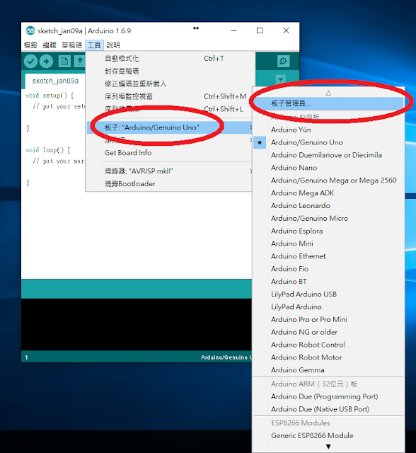
 選擇後後會出現下面這個視窗,選擇2.3.0版本安裝,然後他就會開始跑下載,下在完成後關閉按鈕才會跑出來,這時候才能關掉視窗

若有成功安裝,則板子內會出現許多新的選項

2.連接ESP8266燒錄電路
接下來會需要幾樣工具,麵包版或洞洞板USB轉TTL模組(建議用CH340系列或CP2102系列,較不會燒錄程式失敗)、5V轉3.3V降壓模組或降壓IC,以下是我用的USB轉TTL模組和ESP01版本的腳位圖(黑色板子跟藍色板子的ESP01腳位一樣)


幾個比較要注意的地方
1.ESP8266能接受的電壓3.3V
2.要接3.3V的有ESP8266的VCCCH_PD兩個部分
3.GPIO0要在接上電前接到GND,否則會沒辦法進入燒錄模式
電路如下圖
USB TTL <–> ESP-01
GND               GND
TX                   RX
RX                  TX
3.3V               VCC
 3.3V             CH_PD
GPIO0           GND

3.燒錄Arduino程式到ESP8266內
這裡要先確定你ESP8266的Flash Size,若你的ESP01是藍色的,就選第一個512K(64K SPIFFS),若你的ESP01是黑色的,就選第四個1M(512K SPIFFS)
再來就是Upload Speed,若CH340系列或CP2102系列的USB轉TTL模組,可以選擇921600,若不是CH340系列或CP2102系列的USB轉TTL模組或是上傳一直失敗的同學,請選擇115200,然後甚麼都先不用寫,直接選擇"上傳"按鈕(箭頭那個)
若程式有上傳成功,會出現像下圖的訊息(要在"偏好設定"中,勾選"顯示詳細輸出"的"編譯"和"上傳",才會有橘色字的訊息)

那本篇的教學先到這邊告個段落,下次會繼續寫關於ESP8266程式部分與電路部分,大概內容會以現在目前常見的Arduino模組,將電路與程式碼移植到ESP8266上

參考:
1.Arduino core for ESP8266 WiFi chip
https://github.com/esp8266/Arduino
2.燒錄程式電路圖
http://www.circuitsgallery.com/2016/01/getting-started-with-esp8266-esp-01.html
3.ESP8266模組
http://web-engineering.info/node/65
http://www.esp8266.com/wiki/doku.php?id=esp8266-module-family

2016年4月26日 星期二

樹梅派電源控制開關

一般樹梅派在使用Micro USB介面當作電源輸入時,當Pi執行關機指令(shutdown -h now)後電源還是會持續供電,前一陣子在網路上看到了一個關於樹梅派控制電源的電路,該電路實作結果有點類似PC上的ATX功能,在執行Pi關機後會自動把電源斷電以達到省電的效果。該產品在官網中售價為15歐元約台幣5百多。
本文則是利用該作者所公開的電路圖在所有零件成本不到台幣百元情況下利用洞洞板手工搭棚達到相同功能。

2016年3月15日 星期二

Raspberry Pi 3 Model B 使用心得

系統介紹:
在前一版相隔一年後,樹莓派官方在今年2月29日推出了新版的 Model B 樹莓派稱之為Raspberry Pi 3 Model B,由於目前版本安裝與先前文章以有出入,整理一下安裝的步驟。

2016年2月12日 星期五

[物聯網] URSA IoT模組的初體驗

耕雲推出URSA IoT模組,採用ESP8266晶片設計而成,我們就來測試一下。
打開Aduino先在檔案->偏好設定選單的額外板子管理員網址中輸入http://arduino.esp8266.com/stable/package_esp8266com_index.json,再到工具->板子選單中,開啟板子管理員,找到esp8266進行板子的安裝。
安裝完後就可以在板子選擇Adafruit HUZZAH ESP8266。

首先您要先準備2個硬體設備,URSA IoT模組USB/TTL轉換器
USB/TTL轉換器腳位如下:
1.DTR
2.RXD
3.TXD
4.VCC
5.CTS
6.GND

URSA IoT模組腳位如下(P1 & P2):
P1
1.Tx
2.Rx
3.Gnd
4.1  (GPIO5)
5.2  (GPIO4)
3.3  (GPIO0)
4.4  (GPIO2)
P2
1.5 (5V)
2.3.3 (3.3V)
3.Gnd
4.A (A0)
5.5  (GPIO14)
6.6  (GPIO12)
7.7  (GPIO13)

電路接線如表一

表一、URSA IoT模組和USB/TTL轉換器和腳位對應表
URSA IoT模組USB/TTL轉換器
3.3VCC
GndGnd
RxTxd
TxRxd

在表二的7號上接上LED。

表二、腳位對應表
電路板上的編號Arduino上的宣告
15 (GPIO5)
24 (GPIO4)
30 (GPIO0)
42 (GPIO2) 
514 (GPIO14)
612 (GPIO12)
713 (GPIO13)

我們改寫範例ESP8266Blink上的範例,紅色為修改的內容。
void setup() {
  pinMode(13, OUTPUT);     // Initialize the BUILTIN_LED pin as an output
}

// the loop function runs over and over again forever
void loop() {
  digitalWrite(13, LOW);   // Turn the LED on (Note that LOW is the voltage level
                                    // but actually the LED is on; this is because
                                    // it is acive low on the ESP-01)
  delay(1000);                      // Wait for a second
  digitalWrite(13, HIGH);  // Turn the LED off by making the voltage HIGH
  delay(2000);                      // Wait for two seconds (to demonstrate the active low LED)
}

在進行燒錄時,S2的JUMP必須要朝下。
若使用到GPIO0時,在燒錄完成後,必須要把S2的JUMP朝上。
您不妨把LED換其他腳位測試一下表二上的對應。
注意!JUMP如果在下方的話,重新啟動後會進入燒錄模式,不會執行程式。

2016年1月9日 星期六

[穿戴科技] Adafruit NeoPixel 學習

官方教材:https://learn.adafruit.com/getting-started-with-flora/blink-onboard-neopixel

記得要裝函式庫,可以選擇草稿碼(Sketch)->滙入函式庫(Include Library)->管理函式庫...(Manage Libaries...)安裝 Adafruit_NeoPixel

在官方網站上有程式碼可以複製,程式碼如下:

#include < adafruit_neopixel .h>;

#define PIN 8

Adafruit_NeoPixel strip = Adafruit_NeoPixel(1, PIN, NEO_GRB + NEO_KHZ800);

void setup() {
  strip.begin();
  strip.show(); // Initialize all pixels to 'off'
}

void loop() {
  // Some example procedures showing how to display to the pixels:
  colorWipe(strip.Color(255, 0, 0), 500); // Red
  colorWipe(strip.Color(0, 255, 0), 500); // Green
  colorWipe(strip.Color(0, 0, 255), 500); // Blue
  rainbowCycle(20);
}

// Fill the dots one after the other with a color
void colorWipe(uint32_t c, uint8_t wait) {
  for(uint16_t i=0; i
      strip.setPixelColor(i, c);
      strip.show();
      delay(wait);
  }
}

// Slightly different, this makes the rainbow equally distributed throughout
void rainbowCycle(uint8_t wait) {
  uint16_t i, j;

  for(j=0; j<256 5="" all="" b="" colors="" cycles="" j="" of="" on="" wheel="">
    for(i=0; i< strip.numPixels(); i++) {
      strip.setPixelColor(i, Wheel(((i * 256 / strip.numPixels()) + j) & 255));
    }
    strip.show();
    delay(wait);
  }
}

// Input a value 0 to 255 to get a color value.
// The colours are a transition r - g - b - back to r.
uint32_t Wheel(byte WheelPos) {
  WheelPos = 255 - WheelPos;
  if(WheelPos < 85) {
   return strip.Color(255 - WheelPos * 3, 0, WheelPos * 3);
  } else if(WheelPos < 170) {
    WheelPos -= 85;
   return strip.Color(0, WheelPos * 3, 255 - WheelPos * 3);
  } else {
   WheelPos -= 170;
   return strip.Color(WheelPos * 3, 255 - WheelPos * 3, 0);
  }

}

接下來我們來解釋程式碼的內容

首先我們會看到#include指令。
#include ;
我們使用Google查一下Adafruit_NeoPixel.h,可以發現https://github.com/adafruit/Adafruit_NeoPixel,該專案中可以發現Adafruit_NeoPixel.h和Adafruit_NeoPixel.cpp原始碼,有興趣的是可以看到esp8266.c,很有趣吧!經由敏哥追蹤程式碼,我們發現在Adafruit_NeoPixel.cpp檔案中,可以發現有使用到esp8266.c中的函式espShow()。

#elif defined(ESP8266)

// ESP8266 ----------------------------------------------------------------

  // ESP8266 show() is external to enforce ICACHE_RAM_ATTR execution
  espShow(pin, pixels, numBytes, is800KHz);


#endif // ESP8266

接下來則是使用#define來定義使用到的腳位。

#define PIN 8

隨著物件導向(OO)程式設計廣泛受到大家重視,就連微電腦控制也採用OO的設計方式,不過在建立新物件時,並不需要像C++一樣使用到new關鍵字,Adafruit_NeoPixel就是類別,其建構子有3個參數,分別為LED的數量、硬體連接的腳位、以及LED的型別。

Adafruit_NeoPixel strip = Adafruit_NeoPixel(1, PIN, NEO_GRB + NEO_KHZ800);

以上例來說,只有1個LED,連接在第8支腳,採用GRB,800KHZ通訊訊號的速率。
為何LED跟通訊訊號的速率有關,因為它採用串接方式,當送出10顆LED命令時,接收到的第一顆LED會取下其命令,然後把9個命令再往下送,以此類推。下圖是從https://www.adafruit.com/category/168取得。


接下來則是setup函式,直接呼叫strip物件中,begin函式以及show函式。
void setup() {
  strip.begin();
  strip.show(); // Initialize all pixels to 'off'
}

loop函式裏呼叫2個函式,其一為colorWipe和rainbowCycle兩個函式,前者是固定顏色的顯示,後者則是以顏色變化來顯示。 void loop() {
  // Some example procedures showing how to display to the pixels:
  colorWipe(strip.Color(255, 0, 0), 500); // Red
  colorWipe(strip.Color(0, 255, 0), 500); // Green
  colorWipe(strip.Color(0, 0, 255), 500); // Blue
  rainbowCycle(20);
}
colorWipe第一個參數為顏色值,第二個為延遲的時間。
// Fill the dots one after the other with a color
void colorWipe(uint32_t c, uint8_t wait) {
  for(uint16_t i=0; i
      strip.setPixelColor(i, c);
      strip.show();
      delay(wait);
  }
}

// Slightly different, this makes the rainbow equally distributed throughout
void rainbowCycle(uint8_t wait) {
  uint16_t i, j;

  for(j=0; j<256 5="" all="" b="" colors="" cycles="" j="" of="" on="" wheel="">
    for(i=0; i< strip.numPixels(); i++) {
      strip.setPixelColor(i, Wheel(((i * 256 / strip.numPixels()) + j) & 255));
    }
    strip.show();
    delay(wait);
  }
}

// Input a value 0 to 255 to get a color value.
// The colours are a transition r - g - b - back to r.
uint32_t Wheel(byte WheelPos) {
  WheelPos = 255 - WheelPos;
  if(WheelPos < 85) {
   return strip.Color(255 - WheelPos * 3, 0, WheelPos * 3);
  } else if(WheelPos < 170) {
    WheelPos -= 85;
   return strip.Color(0, WheelPos * 3, 255 - WheelPos * 3);
  } else {
   WheelPos -= 170;
   return strip.Color(WheelPos * 3, 255 - WheelPos * 3, 0);
  }

}